MECHANICAL ENGINEERING
Strip CUTTER - BIKE TYRE
For this project, the customer wanted a device that could cut a strip from a discarded bicycle tire. This strip is then used to make various products.
The tire is hung in the device, after which the width of the strip can be determined by symmetrically moving the knives in and out with the red star wheel.
The red handle is now pulled towards you, causing the blades to cut through the tire. By turning the crank, the tyre is turned around. When the strips have been cut all around, the red handle can be moved away from you and the strip with the two residual products can now be removed.
Manual snap-ring station
Manual Snap Ring station
This machine assembles the Compressor Cover of two Turbochargers types in a controlled way to protect the Compressor Wheel.
The Main assembly is placed in the Jig on the left side. The Compressor Cover (white outside and blue inside) is placed in the lower Jig. The lever is pulled to create a controlled linear motion to press the Compressor Cover over the O-ring of the main assembly. The smaller lever can be rotated to find the pin-to-pin-hole alignment. A snap ring is now manually places to secure the connection between the parts.
Manual SR station on Cabinet
The machine is placed on a table which you can ajust in height. The two collomns hold the Snap Rings of both Turbocharger variants.
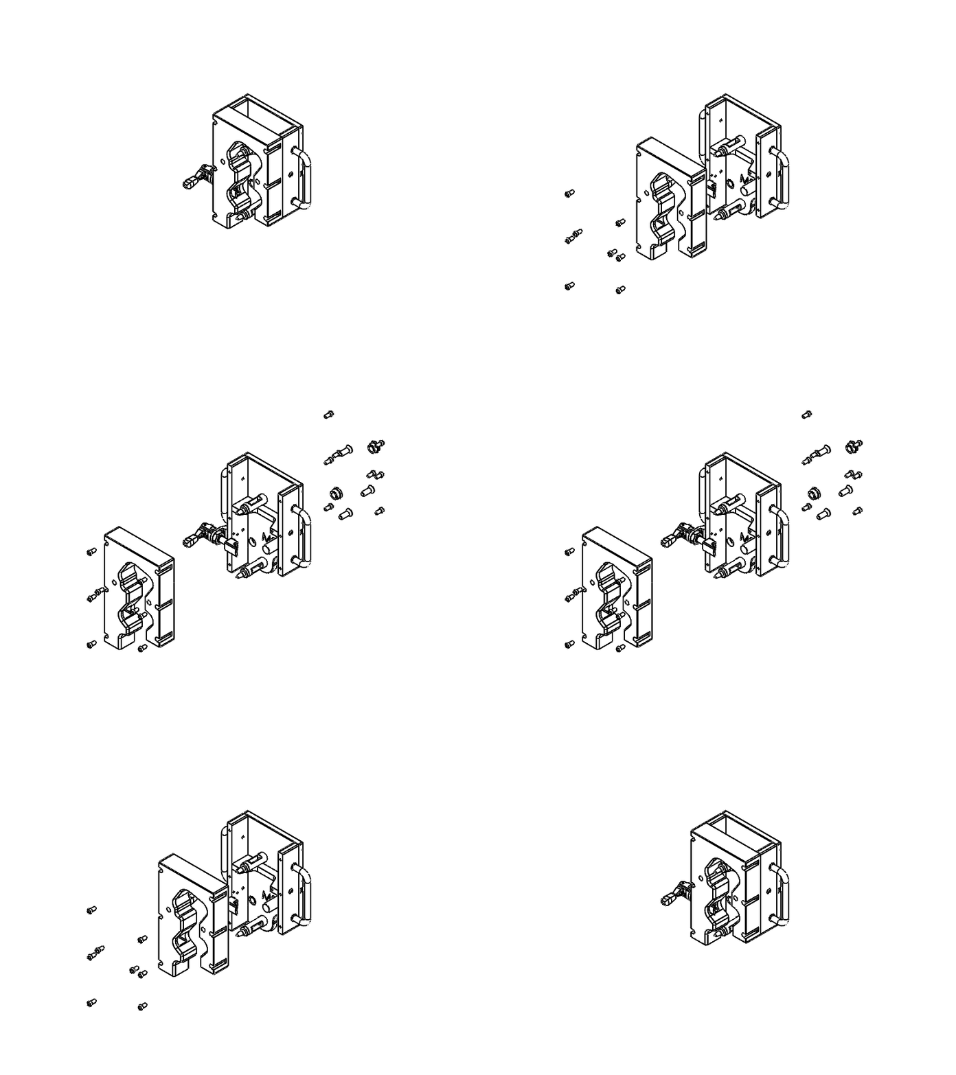
Main assembly JIG
This animation shows the parts of the Main Assembly Jig,
The flange of the Turbine Housing (brown with pink ports) is placed in the contour and clamped with a handle shown on the left.
The Jig is interchangable by releasing to indexing plungers underneath the both handles connected to the main machine.
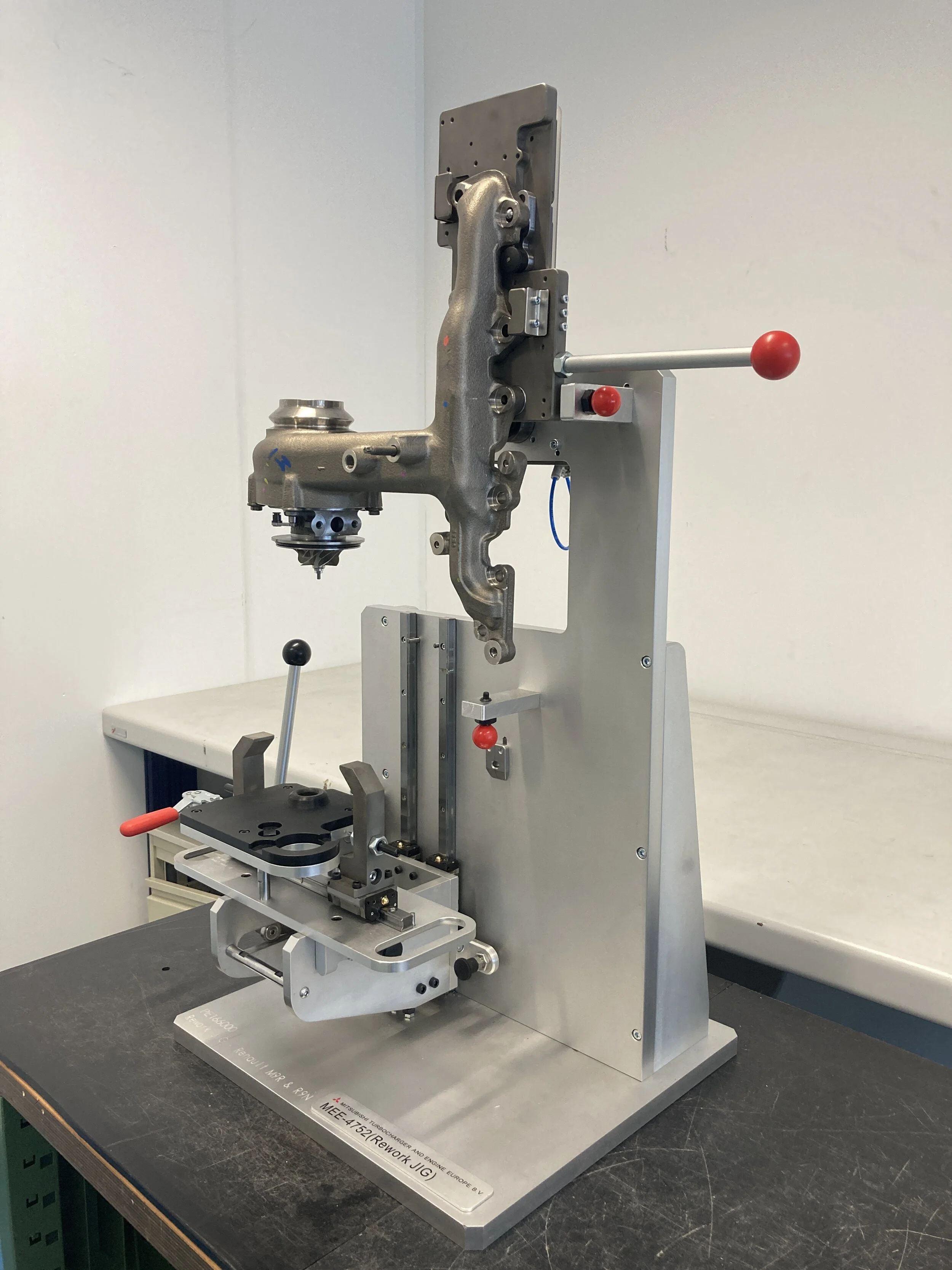
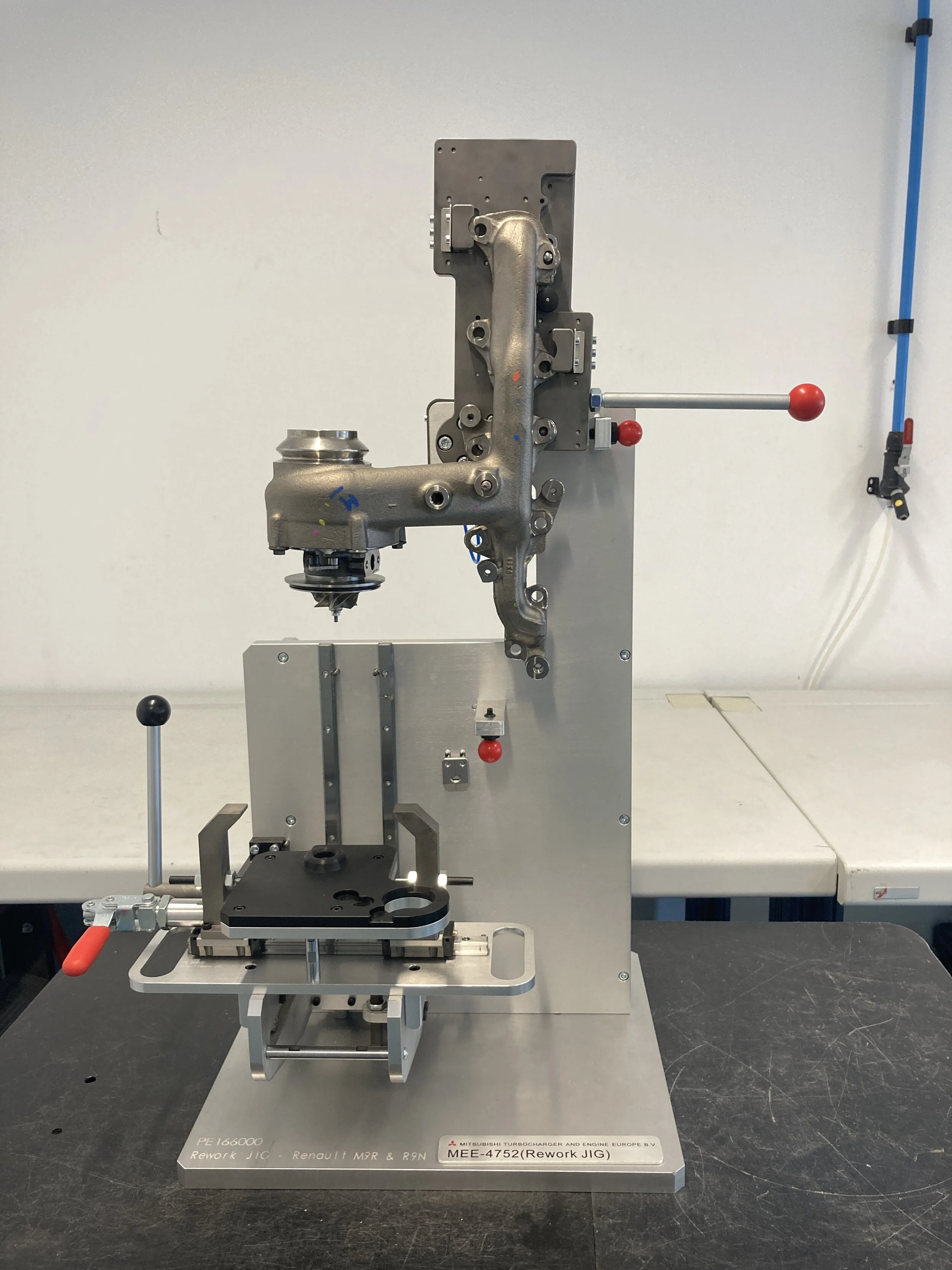
Manual REWORK station
This station is designed to disassemble the compressor from the turbocharger. The complete assembly is clamped on the upper plate. The pneumatic clamps are activated by a foot pedal. With the red handle the assembly can rotate around its center of gravity so both the top and bottom side can be reached.
Clamp activated with pneumatic footpedal
Leaktest station
This semi-automatic station is part of a production-line. This station will check for leakage within a subassembly from the turbocharger.
The components are manually placed in the Jig below. The activation button is pushed. The screen will then automatically be close and the cylinders will cap off all the interfaces. The system will be pressurized and a drop in pressure can now be detected if there is a leakage.


